Introduction
This is completely Optional!
Some of you have access to the T3alliance.org Raspberry Pi Computer Boxes with the included sensor devices, breadboard and other parts. If you do, you can follow along and recreate and improve some of these projects. These are optional. At this point in the course, we have not covered some of the programming concepts involved here. If you copy and paste the program into Thonny and save it, you’ll be able to run it, and control your RPi pins and associated breadboard LEDs if you have those.
The good news is that by the end of the course, you will understand all of the program which I have provided, and I am sure you will discover new ways to control external devices. For now, just consider this a fancy “Hello World” program that instead of printing out a message, lights up some LEDs.
Additional Learning Objectives
- Use a breadboard to create temporary circuits
- Use external devices to communicate the state of a program
- Direct power from specific pin outs on the RPi I/O board
Above is the program in action. I ran the program four times and selected a different pin each time.
The Program
import RPi.GPIO as GPIO
GPIO.setmode(GPIO.BCM)
GPIO.setwarnings(False)
GPIO.setup(4, GPIO.OUT, initial=GPIO.LOW)
GPIO.setup(13, GPIO.OUT, initial=GPIO.LOW)
GPIO.setup(17, GPIO.OUT, initial=GPIO.LOW)
GPIO.setup(18, GPIO.OUT, initial=GPIO.LOW)

answer=input("Which LED do you want to light up? (Enter: 4, 13, 17 or 18) ")
GPIO.output(int(answer),GPIO.HIGH)
Program comments:
- The program uses the RPi.GPIO library with pre-built commands which add to Python’s abilities
- The program starts by letting the RPi know which pins I will be using and automatically turns each to GPIO.LOW which is the same as “OFF”
- The program uses the Input ( ) command to ask the user a number. (This is how it switches the LEDs off/on).
- The program will try to turn the light on, and then quit. If you want to light a different light, just run the program again and provide a different number.
Diagrams
In the picture below, the pins from Raspberry Pi are shown. Each is labeled. This program uses 5 pins:
- #4 wire to Green LED landing at hole 4e
- #13 wire to Yellow LED landing at hole 13e
- #17 wire to Blue LED landing at hole 17e
- #18 wire to Red LED landing at hole 18e
- GND (ground, any pin marked ground will work, but I used the lower left pin)

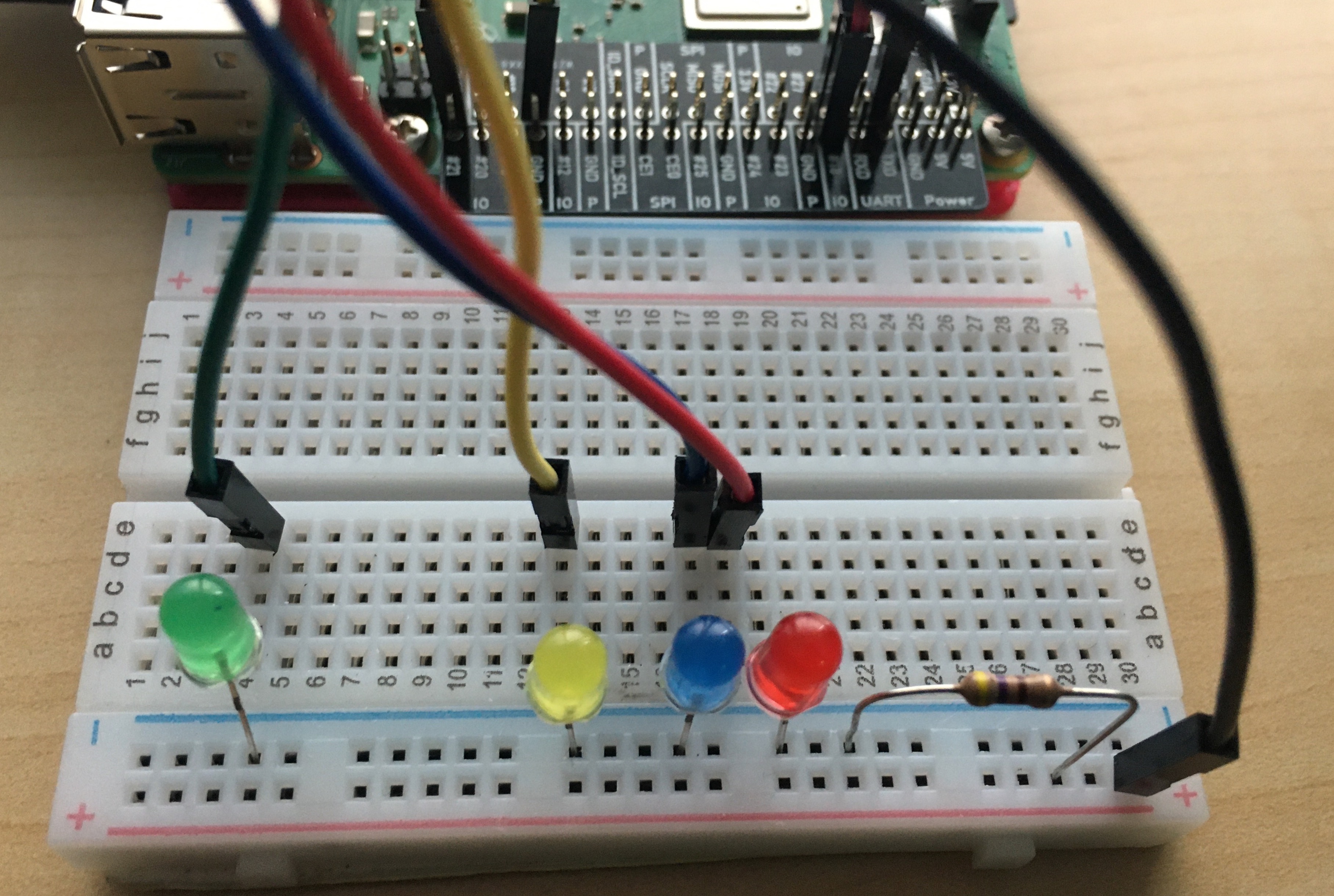
In the picture below is my breadboard near the Raspberry Pi. I used the same color wire as the LED which was being powered. Note that the positive side of the LEDs is longer than the negative side (shorter). All the LEDs have their positive wire placed in the “a” column, and their negative pins (the shorter one), placed in the Blue rail line.
Notice how the resistor connects the Blue rail line with the Red Rail line. Additionally, there is one last wire connecting the Red rail line with the GND pin back on the RPi.
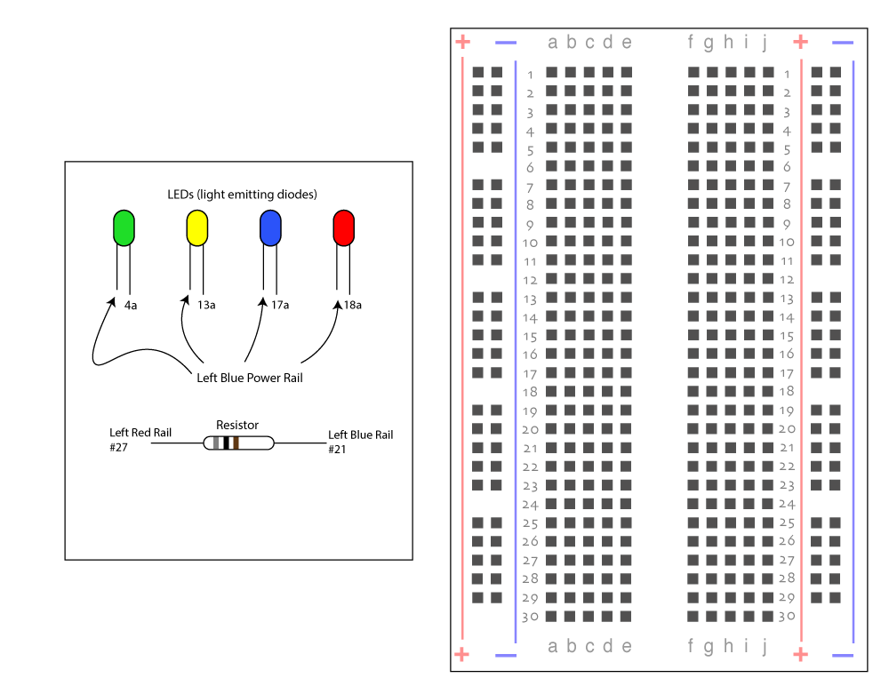
Below is a schematic diagram showing the pin connections on the breadboard. Note that the LEDs have direction. LEDs only allow electricity to flow one way through them (from the longer positive wire, through the bulb, and out the negative shorter wire). Resistors don’t have polarity, current can flow in either direction.
This should be all you need to get this program running, especially if you have experience with the RPi input/output pins.
Questions / Victories
If you’d like to ask a question about this, or would like to share a picture of your working project, please use this discussion thread for RPi GPIO project Part 1.


